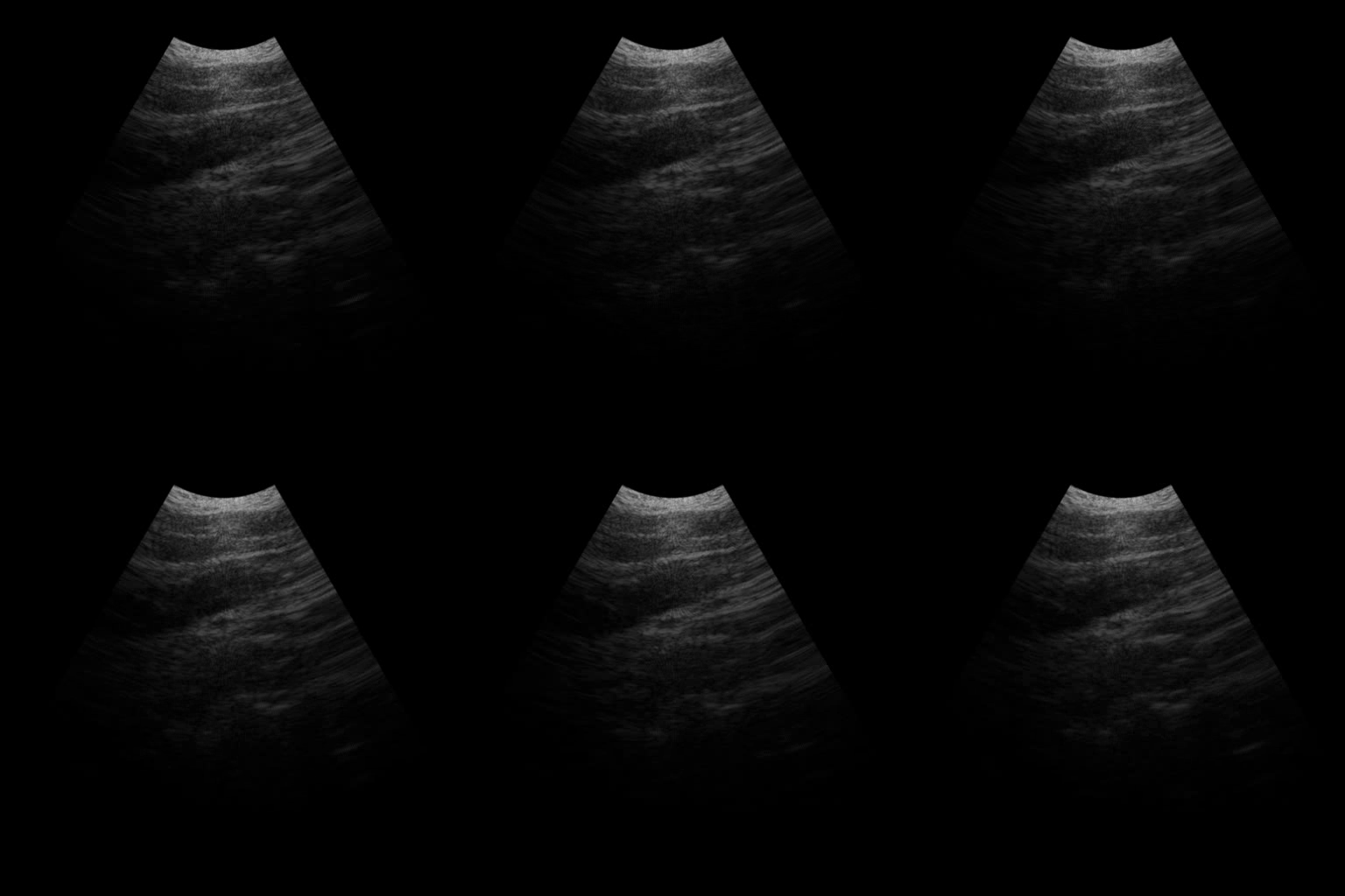
This post is a basic exercise of geometry and image processing.
Ultrasound images are generated based on the probe data of beamwaves reflecting objects in a cone area. Suppose each ultrasound image is consisted with \(C\) waves in different radial directions, and each ultrasound wave records \(L\) points in the range of \([0,255]\), then the raw data can be saved as a \(C \times L\) array. To generate an ultrasound image with \(\theta\) cone angle, we can assume that the radius of the inner circle of the cone area is \(d\) mm, while the outer radius is \(D\) mm. The following figure depicts the parameters of the ultrasound image.
To draw the ultrasound image, first we need to decide the background image size. The height of the image is determined by \(D\). And the width of the image is \(2D\sin\frac{\theta}{2}\) mm. If the angle of the cone is \(60^o\), then the image width should also be \(D\) mm.
With the background image, we need to paint the \(C \times L\) raw probe points into the image. Based on the probe data(\(L\) points) and physical metrics, we can calculate the the number of pixels needed for the background image height and width:
\(h = \frac{DL}{D-d}\),
\(w = \frac{2DL\sin\frac{\theta}{2}}{D-d}\).
And the pixels mapped to the cone’s inner circle radius \(d'\) and outer circle radius \(D'\) are:
\(d' = \frac{dL}{D-d}\),
\(D' = \frac{DL}{D-d}\).
As shown in the above image, we can set the origin to the middle of the image top. Given the \(l\)-th probe data from the \(c\)-th wave, suppose the cone area is painted from left to right, its coordinates \((x,y)\) can be calculated based on the cone’s radius pixels \(d'\) and \(D'\), angle \(\theta\), and number of points \(L\) per cone border:
\(x = \frac{D'}{2} + (d'+l)\cos\alpha\),
\(y = (d'+l)\sin\alpha\).
Where
\(\alpha=\frac{\pi-\theta}{2} + \frac{c\theta}{C-1}\),
is the angle of the pixel to the \(x\)-axis, and \(c=C-1, \cdots, 0\) (from left to right), \(l=0,1,\cdots,L-1\).
The point angle \(\alpha\) is calculated by dividing cone angle \(\theta\) into \(C-1\) copies. For the left half of the cone area, \(\alpha\) is an obtuse angle, hence the above formula still work.
In the real ultrasound image, the origin is set to the upper-left corner. We can shift the origin from the upper middle to left by adding \(\frac{w}{2}\) to each probe data. To make the cone are in the center of the image, we can move each probe data up for \(\frac{d'}{2}\) pixels in the image. Therefore the actual coordinates are:
\(x = \frac{D'}{2} + (d'+l)\cos\alpha + \frac{w}{2}\),
\(y = (d'+l)\sin\alpha - \frac{d'}{2}\).
Following is a short ultrasound video clip generated with the above tranformation method. And here is the python implementation.

